Fuses in the engine compartment
The fuses in the engine compartment help protect electrical components such as engine and brake functions.
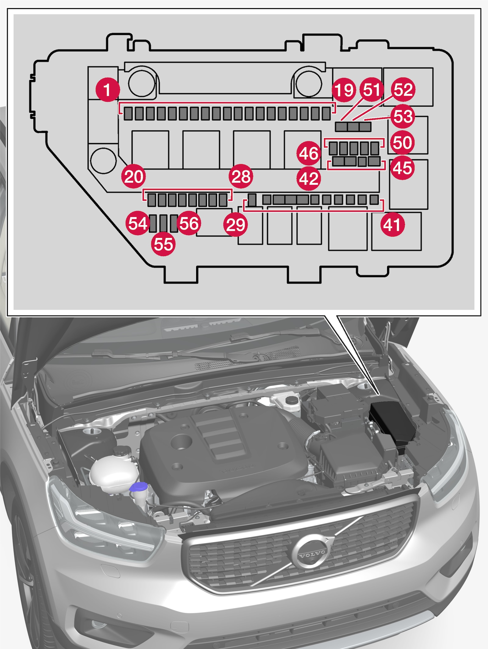
Fuse pliers are provided on the inside of the fuse box cover to assist in removing and inserting fuses.
There are also spaces for several extra fuses in the fusebox.
Positions
There is a decal with a diagram of the locations of the fuses on the inside of the cover.
- Fuses 1–30, 46–50 and 54–56 are "Micro" fuses.
- Fuses 31–45 and 51–53 are "MCase" fuses and should only be replaced by a workshop1.
| Function | Ampere | |
|---|---|---|
 | USB port tunnel console, rear* | 5 |
 | 12 V outlet in tunnel console, front | 15 |
 | – | – |
 | 12 V outlet in trunk/cargo compartment* | 15 |
 | Engine control module | 20 |
 | Ignition coils; spark plugs | 15 |
 | Solenoids (gasoline); valve; Engine cooling system thermostat (gasoline); EGR cooling pump (diesel); glow control module (diesel) Engine control module | 15 |
 | Solenoids (gasoline); Valve; Engine cooling system thermostat (gasoline); EGR cooling pump (diesel); Glow control module (diesel); Vacuum regulators; Valve; Valve for power pulse (diesel) | 10 |
 | Heated oxygen sensor, center (gasoline); Heated oxygen sensor, rear (diesel) | 15 |
 | Nitrous oxide sensor (diesel) | 15 |
 | EGR cooling pump (diesel) | 15 |
 | Right-side headlight | 20 |
 | Left-side headlight | 20 |
 | Airbags | 5 |
 | Accelerator pedal sensor | 5 |
 | Fed when ignition is on: engine control module, transmission components, electrical power steering, central electrical module, brake system control module | 5 |
 | Electric auxiliary heater*; OBD II firewall | 5 |
 | – | – |
 | – | – |
 | Internal relay windings | 5 |
 | – | – |
 | Brake pedal sensor | 5 |
 | – | – |
 | Control module for actuator for engaging/changing gears, automatic transmission | 5 |
 | Transmission control module | 15 |
 | Engine control module | 5 |
 | – | – |
 | – | – |
 | Horn | 20 |
 | Alarm siren* | 5 |
 | Wipers | 30 |
 | Brake system control module (valves, parking brake) | 40 |
 | Brake system control module (ABS pump) | 40 |
 | – | – |
 | Transmission actuator | 25 |
 | – | – |
 | Right-hand headlight; Left-hand headlight | 30 |
 | – | – |
 | – | – |
 | Towbar* control module | 25 |
 | Towbar* control module | 40 |
 | – | – |
 | Power driver seat* | 20 |
 | – | – |
 | – | – |
 | – | – |
 | – | – |
 |
 | – | – |
 | – | – |
 | Fuel filter heater (diesel) | 30 |
 | Heated windshield*, left side | 40 |
 | Heated windshield*, right side | 40 |
 | Support battery check function | 5 |
 | Left-side headlight | 20 |
 | Right-side headlight | 20 |